



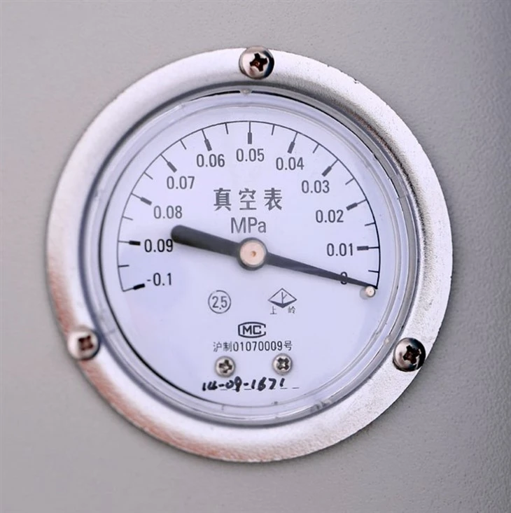


Lab Vacuum Drying Oven
(a)10 series
Lab Scales Desktop(Freeze-dried material 1.5-2KG)
(b)12 series
Lab Scales Vertical(Freeze-dried material 2KG)
(c)18 series
Scientific Research Scales(Freeze-dried material 3KG)
2.Pilot Freeze Dryer:
0.2m²/0.3m²/0.5m²/1m²/2m²/---Pilot Scales(Freeze-dried material 3KG-20KG)
3.Customization: set up the specifications you need
(a)Freeze-dried Area
(b)Freeze-dried Weight
(c)Freeze-dried Material
(d)Interlayer Quantity/Size
(e)Cold Trap Temperature
Description
Technical Parameters
In the vast fields of scientific research and industrial production, vacuum drying technology is widely used due to its unique advantages. Especially in laboratory environments, Lab Vacuum Drying Oven have become indispensable equipment for samples with high purity, thermal sensitivity, susceptibility to oxidation, or containing complex components. However, traditional vacuum drying ovens often face problems such as condensed water accumulation, high energy loss, and inconvenient sample extraction during long-term operation. In response to these pain points, this utility model proposes an innovative laboratory vacuum drying oven water removal device, aiming to achieve effective removal of condensed water, reduce energy loss, and improve the processing efficiency of samples after drying through optimized structural design.

Product Structure & Model
Lab Vacuum Drying Oven technology utilizes the principle of reducing the boiling point of volatile substances such as water in a vacuum state to quickly remove moisture from materials at lower temperatures, avoiding adverse reactions such as material denaturation and oxidation that may occur at high temperatures. However, in a vacuum environment, as moisture evaporates, condensed water will accumulate inside the drying oven. If not treated in a timely manner, it will not only affect the drying effect but may also cause damage to the equipment. In addition, frequent opening of doors to remove condensed water can lead to a significant loss of energy and increase operating costs. Therefore, it is particularly important to develop an efficient and energy-saving vacuum drying oven water removal device.
|
|
|
|
|


In order to solve the above problems, a new type of laboratory vacuum drying oven water removal device was designed to achieve automatic collection and removal of condensed water, while optimizing the sample placement and removal methods, improving drying efficiency and operational convenience. The device mainly consists of core components such as a drying oven, water storage tank, tray support, and guide groove. These components work together to form an efficient and stable vacuum drying system.
Device structure and working principle
1. Design of drying oven and drying room
The core of this device is the drying oven, which has a carefully designed drying chamber inside. The bottom of the drying chamber is connected to the water reservoir through an inlet pipe, and the bottom is inclined towards the location of the water reservoir. This design cleverly utilizes the effect of gravity, allowing the condensed water generated during the vacuum drying process to flow smoothly into the water storage tank, avoiding the accumulation of condensed water in the drying chamber.
2. Water storage tank and valve system
The water reservoir is located below the drying oven and is used to collect and store the condensed water discharged from the drying chamber. The water storage device is equipped with a condensate inlet valve and a condensate outlet valve. By controlling the opening and closing of these two valves, flexible adjustment of the condensate collection process can be achieved. When it is necessary to discharge condensed water, simply open the outlet valve without opening the drying oven door, effectively reducing energy loss.
3. Design of drying chamber top and guide groove
The top of the drying chamber is designed as an arc-shaped structure with an opening facing the drying chamber, which is conducive to the natural convergence and drainage of condensed water. At the same time, there are multiple guide grooves on the back wall of the drying chamber, which further guide the condensed water gathered at the top to the bottom of the drying chamber, and finally discharge it into the water reservoir through the inlet pipe. The setting of the diversion groove not only improves the efficiency of condensate removal, but also avoids the disorderly flow and dripping of condensate in the drying room.
4. Tray support and sample placement
The tray bracket is located at the top of the drying chamber and is used to support the tray for placing samples. There is a certain distance between the tray bracket and the back wall of the drying chamber, which not only provides space for the flow of condensed water, but also facilitates the placement and removal of samples. The design of the tray fully considers the shape and size of the sample, ensuring that the sample can be uniformly heated and maintain a good fluffy state during the drying process. In addition, the material and structure of the tray bracket have been carefully selected and optimized to ensure its stability and durability.
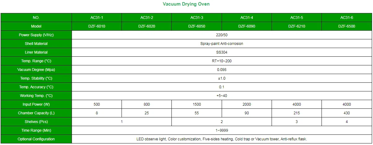
Product Parameter
Technological innovation points
1. Bottom design of inclined drying chamber
By tilting the bottom of the drying chamber towards the location of the water reservoir, this utility model achieves natural flow and collection of condensed water. This design not only simplifies the process of condensate removal but also reduces energy loss and the need for manual intervention.
2. The synergistic effect of the curved top and the guide groove
The arc-shaped design at the top of the drying chamber and the flow guide groove on the rear wall work together to form an efficient condensate collection and guidance system. This system ensures that condensed water flows quickly and orderly towards the bottom of the drying chamber and ultimately into the water storage tank.
3. Optimization design of tray bracket
The design of the tray bracket fully considers the convenience of placing and removing samples. By reasonably setting the distance between the tray bracket and the back wall of the drying chamber, and optimizing the structure and material of the tray, this utility model improves the fluffiness and removal efficiency of the dried samples.
Application advantages
Advantages of Chain Sprockets
1. Improve drying efficiency and quality
Due to the timely removal of condensed water and the reduction of energy loss caused by frequent door opening, the lab vacuum drying oven water removal device of this utility model can significantly improve drying efficiency and quality. Meanwhile, maintaining a fluffy state during the drying process of the sample is beneficial for subsequent processing and analysis.
2. Reduce operating costs and maintenance difficulty
The utility model reduces the operating cost of the equipment by reducing energy loss and simplifying the process of condensate removal. In addition, due to the reasonable structural design and appropriate material selection, the maintenance difficulty of this device is relatively low.
3. Improve operational convenience and safety
The optimized design of the tray bracket makes the placement and removal of samples more convenient while also improving operational safety. In addition, by reducing the need for frequent door opening, this device also lowers the direct contact time between operators and the vacuum environment, thereby reducing potential safety risks.
Application Cases and Effect Evaluation
In order to verify the actual effect of the laboratory vacuum drying oven water removal device of this utility model, we selected multiple samples from different fields for drying experiments. The experimental results show that the device performs well in drying efficiency, sample quality, and ease of operation. Specifically:
The drying efficiency is significantly improved:
Compared to traditional vacuum drying ovens, this device can complete more sample drying work in the same time and achieve better drying results.
The quality of the sample is guaranteed:
Due to the timely removal of condensed water and the reduction of high temperature exposure time, the purity and stability of the sample are effectively guaranteed.
Enhanced operational convenience:
The optimized design of the tray bracket makes sample placement and retrieval easier and faster, while also reducing the labor intensity of operators.
In summary, the lab vacuum drying oven water removal device proposed by this utility model achieves effective removal of condensed water and efficient utilization of energy through innovative structural design and optimized workflow. This device not only improves drying efficiency and quality, but also reduces operating costs and difficulty, providing a new solution for vacuum drying technology in laboratory environments. In the future, with the continuous progress of science and technology and the expansion of application fields, we have reason to believe that this device will play an important role in more fields and promote the further development of vacuum drying technology.
Electrical safety code
Power supply configuration specifications
Power supply voltage and capacity
The power supply voltage must be consistent with the rated voltage of the device (for example, 220V/50Hz or 380V/50Hz), and the power supply capacity must meet the power requirements of the device (for example, ≥3kW).
Do not share the same power socket with other high-power devices to prevent voltage fluctuations or overload.
Ground protection
The device shell must be reliably grounded through a dedicated ground cable with a grounding resistance ≤4 ohms to prevent electric shock caused by leakage.
Use a copper conductor with a cross-sectional area greater than or equal to 2.5mm² for grounding cables, and check the grounding status periodically.
Safety specifications for electrical components

Electrical insulation
Periodically check the insulation performance of power cables, plugs, and internal electrical components. The insulation resistance should be greater than or equal to 1MΩ.
Do not use damaged or aged power cables. Replace the insulation layer immediately if it is found to be cracked.

Leakage protection
Install the leakage protection switch (leakage action current ≤30mA, operation time ≤0.1s) to ensure that the power can be quickly cut off when leakage.
Test the sensitivity of the leakage protection switch monthly to ensure its normal operation.

Overload protection
Equipment should be equipped with overload protection devices (such as thermal relays) to prevent damage to the motor or heating element due to overload.
Do not overload the device for a long time.
Operation and maintenance specifications
Preoperation check
Before powering on the power, check whether the power cable is firmly connected, whether the plug is loose, and whether the control panel display is normal.
Do not open the door of the electrical control box when the device is powered on.
Maintenance requirement
Clean the dust on the surface of electrical components regularly to prevent short circuit or overheating caused by dust accumulation.
Every year, a professional electrician conducts a comprehensive inspection of the electrical system, including line aging, contactor contact wear and other conditions.
Safety specifications for special scenarios
Use in humid environment
In a laboratory with high humidity, use a moisture-proof socket, and ensure that the bottom of the device is at least 10cm away from the floor to prevent moisture.
Do not spray water or corrosive liquid on the device surface.
Restart after being disabled for a long time
After the equipment is disabled for more than 3 months, a professional electrician should check the insulation performance of the electrical system and confirm that it is normal before it can be powered on.
Safety identification and training
Safety sign
Post warning signs such as "High voltage danger" and "No live operation" in the obvious position of the equipment.
Electrical schematics and operation instructions should be posted inside the electrical control box.
Operator training
Operators must receive electrical safety training and be familiar with the structure of the electrical system and emergency handling methods.
Non-professional personnel are prohibited from disassembling or repairing electrical systems.
Summary
The electrical safety of lab vacuum drying oven needs comprehensive management from many aspects such as power supply configuration, component protection, operation and maintenance and personnel training. Strict compliance with the above specifications can effectively reduce the risk of electrical failure and ensure the safety of equipment and personnel.
Hot Tags: lab vacuum drying oven, China lab vacuum drying oven manufacturers, suppliers, factory, Stainless Steel Pressure Reactor, Jacketed Glass Reactor Vessel, 5l Rotovap, Stainless Steel Chemical Reactor, Chemical Equipment, Short Path Molecular Distillation
Previous
Vacuum Drying ChamberNext
Lab Vacuum DryerSend Inquiry


